
Featured OEM Variable Frequency Drive Motors & Systems
Explore our precision-engineered VFD motors, explosion-proof asynchronous drives, vector control inverters, and high-torque AC servo solutions engineered for severe duty applications.
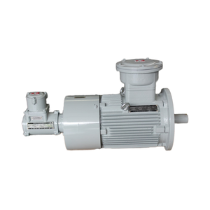
EAC CUTR Explosion-Proof VFD Three-Phase Asynchronous Motor YBBP Series 280KW 460/480V 5-100Hz
Get a Quote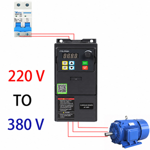
High Quality VFD 220V Single Phase to 3 Phase 380V 0.75KW-7.5KW Vector Control Variable Frequency Inverter AC Motor
Get a Quote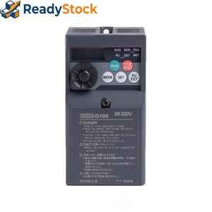
New Original FR-D720S-014-EC VFD 0.2KW 0.25HP Single-Phase 200V Vector Control Variable Frequency Drive Motor Stock
Get a Quote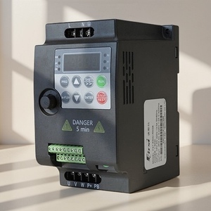
High Performance 1.5KW-11KW Three Phase 380V VFD Machine-Controlled Speed Regulation Motor
Get a Quote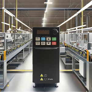
Industrial Grade 2.2KW Single Phase VFD Wide Voltage Design (220V/380V) Energy-Saving Powerful Motor
Get a Quote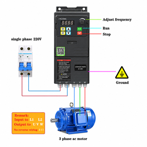
220V 380V Single Phase VSD Variable Speed Drive VFD Frequency Inverter For Motor 1HP-7.5HP Vector Control
Get a Quote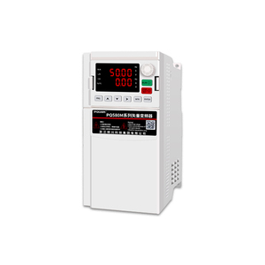
PQUAN PQ580M-3T1.5GB 1500W IP20 PWM Control Three/Single Phase ACIM/PMSM Motors Speed Drive VFD
Get a Quote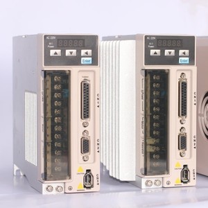
80ST-H02430 Servo Motor Kit 750W AC Driver 220V Durable Quiet High-Torque Variable-Frequency Drive
Get a QuoteComprehensive Technical Whitepaper: Custom OEM Variable Frequency Drive Motors Sourcing
As heavy manufacturing, energy production, municipal water treatment, and mining automation shift toward high-efficiency dynamic motion control, the demand for Custom OEM Variable Frequency Drive Motors has grown exponentially. Standard off-the-shelf motors deployed alongside variable frequency drives often suffer from partial discharge degradation, excessive bearing fluting, localized overheating at reduced speeds, and accelerated winding breakdown. Procurement officers and plant operations managers require tailored motor architectures designed ground-up for variable speed regulation, strict thermal management, and extreme ambient resilience.
1. Technical Architecture of OEM VFD Duty Motors
A true OEM VFD motor is not merely a standard induction motor attached to an inverter board; it incorporates specific mechanical and electromagnetic enhancements engineered to withstand non-sinusoidal voltage waveforms. Pulse Width Modulation (PWM) from modern insulated-gate bipolar transistor (IGBT) inverters delivers high-frequency voltage pulses with steep risetimes ($dv/dt$). Without adequate design protections, these pulses induce severe voltage reflections at motor terminals, exceeding peak dielectric breakdown thresholds.
Corona-Resistant Magnet Wire
Utilizing inverter-duty magnet wire coated with polyimide-over-polyester-imide film enamel prevents micro-arcing and partial discharge breakdown under high $dv/dt$ conditions (exceeding 1600V peak pulses per NEMA MG1 Part 31 standards).
Bearing Fluting Mitigation
High-frequency common-mode voltages induce current flow through motor bearings. OEM VFD configurations integrate ceramic insulated bearings or conductive micro-fiber shaft grounding rings (SGR) to safely divert shaft voltage and eliminate pitting.
Constant-Torque Auxiliary Cooling
At low operating frequencies (e.g., 5-15 Hz), integrated shaft fans lose velocity and cooling capability. OEM VFD motors utilize independently powered constant-speed blowers (TEBC) to maintain thermal equilibrium across continuous zero-speed torque demands.
2. Technical Specifications & OEM Customization Matrix
To assist industrial procurement engineering, the table below contrasts core specifications across our standard OEM VFD product lines, highlighting critical parameters necessary for correct drive matching and installation safety.
| Motor Class / Series | Power Rating Range | Voltage & Frequency Range | Enclosure & IP Rating | Turndown Ratio (CT / VT) | Key OEM Application Focus |
|---|---|---|---|---|---|
| Explosion-Proof YBBP Series | 1.5 KW to 280 KW+ | 380V / 460V / 480V (5-100Hz) | Cast Iron IP55 / IP56 (EAC CUTR) | 10:1 CT / 20:1 VT | Hazardous chemical, oil & gas, underground mining pumps |
| Vector Inverter AC Systems | 0.75 KW to 11 KW | Single Phase 220V to 380V 3Ph | Aluminum / Steel IP20 to IP54 | 100:1 Open Loop Vector | Industrial machinery, conveyors, HVAC fans, spindle drives |
| Micro-Precision FR Series | 0.2 KW to 2.2 KW | Single Phase 200V / 220V | Compact Enclosed IP20 | 1000:1 Closed Loop | Precision automated processing, laboratory equipment, robotics |
| PQUAN Speed Drive ACIM/PMSM | 0.75 KW to 7.5 KW | 220V / 380V Dual Rating | Ruggedized IP20 PWM Control | Full Dynamic Vector | Hybrid Permanent Magnet & Induction motor regulation |
| 80ST Servo Motor Driver Kit | 750W (0.75 KW) | 220V Single/Three Phase | Sealed IP65 Motor Unit | Infinite Digital Speed Control | High-torque positioning, CNC milling, precision dosing pumps |
3. Global Sourcing Trends in VFD Motors & Electric Machinery (2025–2030)
The global industrial drive market is undergoing a structural transition towards integrated intelligent motion systems. Major international engineering firms and procurement directors prioritize the following four technological vectors:
- Transition to IE4 Super Premium & IE5 Ultra-Premium Efficiency: Global decarbonization targets and strict energy codes (such as EU Ecodesign directives) demand that OEMs manufacture VFD motors with significantly reduced active copper and iron losses. Combining synchronous reluctance (SynRM) and permanent magnet architectures (PMSM) with VFD control achieves IE5 efficiency ratings even under partial load profiles.
- Integration of Wide-Bandgap Semiconductor Inverters (SiC & GaN): Modern variable frequency drives are migrating from traditional Silicon IGBTs to Silicon Carbide (SiC) MOSFETs. This transition elevates switching frequencies up to 50 kHz, requiring OEM motor manufacturers to utilize advanced slot insulation, phase separators, and custom-wound stator structures capable of handling extreme voltage rise times without corona degradation.
- IIoT Embedded Predictive Diagnostic Sensors: Future-ready VFD motor designs incorporate internal winding temperature sensors (PT100/RTD), tri-axial vibration transducers, and magnetic flux sensors directly into the stator frame. Real-time data streams to edge VFD drives for AI-driven predictive maintenance, preventing catastrophic bearing or insulation failures before they cause unexpected factory shutdown.
- Supply Chain Resilience & Custom OEM Adaptation: Industrial buyers are moving away from rigid commodity motor lines in favor of agile OEM suppliers capable of engineering custom shaft dimensions, non-standard mounting flanges (NEMA / IEC combinations), multi-voltage windings (220V/380V/460V/660V), and regional explosion-proof certifications (EAC, ATEX, IECEx, UL).
Enterprise Manufacturing Advantages & Engineering Heritage
Backed by over a century of industrial electric motor leadership, state-of-the-art manufacturing facilities, and strict adherence to international quality standards.
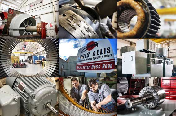
Centennial Reliability & Custom Engineering Leadership
Traced to a rich industrial heritage established in 1901, our partner manufacturing facilities—including the renowned Louis Allis tradition in Warrior, Alabama—possess unmatched technical expertise in engineering, custom manufacturing, and remanufacturing Above NEMA AC and DC motors reaching up to 20,000 HP.
Our ISO 9001:2015 certified production processes adhere strictly to NEMA MG1, IEEE 841, EASA AR100, MIL-SPEC, and UL safety standards. Whether supplying standardized 0.75KW vector drives or engineering one-off 280KW explosion-proof VFD motors for hazardous marine or mining environments, every motor undergoes rigorous full-load testing, surge testing, vibration spectrum analysis, and dielectric VPI verification before global dispatch.
Full OEM Customization
Engineering specialized mechanical shafting, custom foot/flange mountings, anti-corrosive epoxy treatments, dual-keyways, and specialized encoder mounting brackets tailored to exact application geometries.
MIL-SPEC & Hazardous Area Ready
Capability to build MIL-STD-2037 Navy sealed winding systems, ATEX / EAC CUTR explosion-proof motors, and extreme temperature thermal barrier motor frames for heavy offshore or defense operations.
Complete In-House Testing Facility
Every VFD motor undergoes dynamic load testing, thermal rise measurement, high-potential dielectric breakdown verification, and automated harmonic distortion checking to ensure zero out-of-box failures.
Frequently Asked Questions (FAQ) - VFD Motor Procurement
Addressing key engineering, operational, and procurement queries regarding custom OEM variable frequency drive motor selection and drive integration.
What is the difference between a standard AC induction motor and an OEM VFD-duty motor?
Standard AC induction motors are optimized for continuous 50Hz or 60Hz sinusoidal power. When connected to a VFD drive, standard motors suffer from overheating at reduced speeds due to diminished fan velocity, and their insulation rapidly degrades under PWM high-voltage spikes ($dv/dt$). OEM VFD-duty motors feature inverter-grade Class H insulation wire, heavy-duty VPI impregnation, insulated bearings to prevent shaft current pitting, and optional blower-forced cooling for continuous zero-speed torque operation.
How does an OEM manage shaft voltages and bearing currents in high-power VFD motors?
High switching frequencies in modern inverters generate common-mode voltages that capacitively couple onto the motor shaft, leading to discharge through motor bearings (bearing fluting). In our custom OEM VFD motors (especially units above 75KW / 100HP), we install ceramic insulated non-drive-end bearings alongside micro-fiber shaft grounding rings (SGR) on the drive end, safely dissipating stray currents to earth ground.
Can single-phase supply voltage power a three-phase VFD motor system?
Yes. OEM VFD vector control inverters (such as our 220V single-phase to 380V three-phase VFD units) synthesize three-phase AC power from a single-phase utility supply via DC-bus voltage doubling circuits. This enables small workshops, light industrial plants, and agricultural operations to run high-torque 3-phase AC asynchronous motors without incurring costly utility three-phase line expansion.
What is the standard turndown ratio, and why is thermal rating important?
Turndown ratio indicates the speed range over which a VFD motor can maintain continuous torque without exceeding safe temperature limits. A 10:1 CT (Constant Torque) ratio allows a 60Hz motor to run at 6Hz with full load torque. For severe 1000:1 or 20:1 CT requirements, our OEM engineers equip the motor with forced-ventilation blowers (TEBC) and Class H thermal insulation capable of 200°C thermal protection.
Are explosion-proof VFD motors (such as the YBBP series) suitable for variable speed in hazardous locations?
Yes. The YBBP Series EAC CUTR / ATEX certified explosion-proof VFD motor is specifically designed for explosive gas or combustible dust atmospheres (Zone 1, Zone 2, Class I Div 1). The flameproof enclosure withstands internal explosion pressure without allowing flame propagation, while specialized thermal sensors continuously monitor frame temperature under variable speed operation.
What cable length precautions should be taken between the VFD inverter and motor?
Long cable leads (exceeding 50 meters or 160 feet) create impedance mismatches, causing reflected voltage waves that double the peak voltage at motor terminals (reaching 1600V-2000V). For long cable distances, our OEM application team recommends inserting a $dv/dt$ filter or sine-wave filter at the drive output, along with specifying our NEMA MG1 Part 31 compliant motor insulation systems.
Request a Custom OEM VFD Motor Engineering Quote
Need specialized voltage ratings, explosion-proof certifications, high-powerAbove NEMA frames, or tailored vector drive packages? Our senior electrical engineering team is ready to analyze your exact duty cycle and deliver a competitive OEM quote.