
Featured Industrial Vibration & Explosion-Proof Motor Systems
Explore our top-performing custom electric motors and vibrating drive units manufactured for extreme load capacities, continuous duty cycle, and volatile hazardous environments.
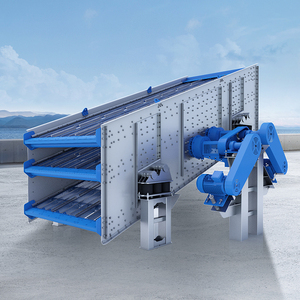
Aggregate Vibrating Screen Machine for Stone Crusher Plant 60-350t/h Ore Processing 30kW Motor High Output Finished Sand
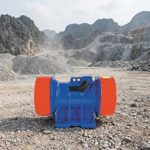
Vibrating Screen Vibrating Feeder & Hopper Vibration Motor for Ore Processing Heavy Load Capacity Durable Engine
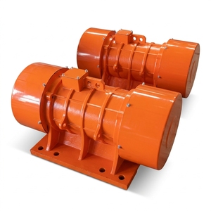
Three Phase Vibration Motor IP65 Waterproof Adjustable Exciting Force for Vibrating Screen Silo Hopper Mining Cement Machinery
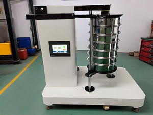
High-Accuracy Stainless Steel Laboratory Rotap Sieve Shaker Vibrating Motor Circular Vibrating Screen for Particle Size
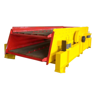
DUOLING Circular Vibrating Screen AC Motor 1-200 Tons Capacity Long Working Life for Ore Core Component Bearing Mining Screening
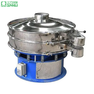
Durable Stainless Steel Rotary Vibrating Screen Motor-Easy-Clean for Food Processing (Dried Fruit Wheat Flour Sieving)-380V/220V

Multi-Layer Rotary Vibrating Screen Vibration Motor | Kaolin Clay Processing | 1-5 Decks Customizable | 100-500 Mesh Industrial
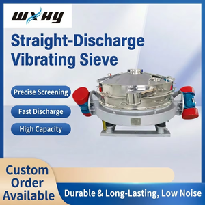
HY-1200-1s Direct Discharge Motor Vibrating Screen 380V Industrial-Grade OEM Heavy Duty Power Unit
Custom Electric Motor Manufacturing & Reverse Engineering Excellence
Leveraging over a century of specialty electric motor heritage (originating from our renowned Louis Allis engineering lineage), we manufacture, remanufacture, and customize high-voltage and low-voltage explosion-proof electric motors designed for non-stop industrial operations.
Certified Explosion-Proof Enclosures
Engineered to contain internal explosions without igniting surrounding flammable vapors, dust, or gases. Fully compliant with ATEX, IECEx, UL Class I Div 1/2 (Groups A, B, C, D) and Class II Div 1/2 (Groups E, F, G).
Tailored OEM & Drop-In Dimensions
Custom mechanical mounting footprints, shaft extensions, terminal box relocations, and custom flange setups designed to replace obsolete or end-of-life legacy motors with zero structural modification to your plant floor.
Inverter-Duty & High-VPI Insulation
Class H and Class H+ Vacuum Pressure Impregnation (VPI) winding insulation with insulated bearings and shaft grounding rings to eliminate electrical fluting damage from modern Variable Frequency Drives (VFDs).
Severe Duty Vibration Resistance
Features heavy-ribbed cast-iron or fabricated steel frames, reinforced end-bells, oversized bearings, and dynamic 2-plane balancing to survive severe g-force vibrations in aggregate screens, mills, and crushers.
Full Load & Environmental Testing
Every custom OEM motor undergoes full load testing, winding surge analysis, thermal rise profiling, vibration frequency spectrum check, and hydrostatic flame-path verification prior to factory dispatch.
Global Sourcing & Outage Support
Providing rapid emergency replacements, field engineering diagnostics, and global lifecycle support to minimize unplanned downtime in high-consequence energy, mining, and manufacturing facilities.
Industry Whitepaper: Engineering Custom OEM Explosion-Proof Electric Motors for Volatile Environments
1. Protection Concepts: Decoupling Ignition Sources from Hazardous Atmospheres
In chemical refineries, underground coal mines, grain processing facilities, and offshore drill rigs, electric motors operate in environments where explosive air-gas mixtures are constantly or intermittently present. An electric motor is a potential ignition source due to internal electrical arcing, rotor surface temperatures, terminal connection friction, or winding insulation breakdown.
To mitigate these explosive risks, international standards—such as IEC 60079 across Europe/Asia and NFPA 70 (NEC Article 500/505) in North America—specify mandatory enclosure construction philosophies:
| Protection Type | IEC/ATEX Code | NEC / UL Designation | Operating Principle & Key Design Characteristics |
|---|---|---|---|
| Flameproof | Ex d | Class I, Div 1 (Explosion-Proof) | Enclosure withstands internal explosion pressure without rupturing; precisions-machined flame paths cool escaping gases below ignition point. |
| Increased Safety | Ex e | Class I, Zone 1 (Ex e) | Prevents internal arcs, sparks, or excessive surface temperatures through boosted electrical clearances, high IP ratings, and thermal margins. |
| Pressurized / Purged | Ex p | Class I, Div 1/2 (Type X, Y, Z Purge) | Maintains positive internal overpressure using inert gas (nitrogen or clean air) to prevent combustible gases from entering the frame. |
| Dust Ignitionproof | Ex tb / Ex tc | Class II, Div 1/2 (Dust-Tight) | Tight labyrinth seals and O-rings restrict dust entry (IP65/IP66) while limiting maximum exterior surface temperature. |
2. Flame-Path Mechanics & Mechanical Integrity in Ex d Enclosures
The cornerstone of a custom OEM Flameproof (Ex d) motor is the flame path (or flameproof joint). A common misconception is that an explosion-proof motor is air-tight. In reality, explosive vapors enter the motor interior during thermal breathing cycles. If an internal arc ignites the gas, the enclosure must contain the violent pressure wave while forcing expanding hot combustion gases through engineered metal clearance gaps.
As these hot gases traverse the tight labyrinth of the shaft seals, bearing caps, and flanged frame joints, heat energy is rapidly transferred into the heavy cast-iron or fabricated steel body. By the time the gas exits the enclosure exterior, its temperature is dropped below the Minimum Ignition Temperature (MIT) of the surrounding atmospheric gas group (e.g., Propane, Ethylene, Hydrogen, or Acetylene).
Our custom OEM manufacturing facility employs multi-axis CNC turn-mill centers to machine flame paths with tolerances measured in micrometers (µm). Key parameter checks include:
- Flame Path Gap Width (i): Controlled strictly between 0.05 mm and 0.20 mm depending on gas group (Group IIA, IIB, or IIC).
- Flame Path Joint Length (L): Engineered joint lengths ranging from 9.5 mm up to over 25 mm based on internal free volume calculations.
- Surface Roughness (Ra): Machined smooth to Ra ≤ 6.3 µm to prevent turbulent heat accumulation and structural flame bypass.
| Gas Group | Representative Gas | Auto-Ignition Temp (°C) | Required Enclosure Flame Gap Standard |
|---|---|---|---|
| Group IIA / Class I Group D | Propane / Methane | 470 °C | Standard Flame Gap (≤ 0.30 mm) |
| Group IIB / Class I Group C | Ethylene | 425 °C | Medium Flame Gap (≤ 0.20 mm) |
| Group IIC / Class I Group B | Hydrogen / Acetylene | 560 °C / 305 °C | Ultra-Tight Labyrinth Flame Gap (≤ 0.10 mm) |
3. Temperature Classes (T-Codes) & Insulation Thermal Management
In hazardous location motor specification, controlling maximum exterior surface temperature is paramount. If a motor’s outer casing exceeds the auto-ignition temperature of ambient dust or vapor, catastrophic fires occur—even without an open flame.
Motors are classified under Temperature Codes (T1 through T6). A higher T-code rating indicates a lower maximum surface temperature limit, ensuring safer operation in low auto-ignition chemical environments:
T1 (≤ 450°C) | T2 (≤ 300°C) | T3 (≤ 200°C) | T4 (≤ 135°C) | T5 (≤ 100°C) | T6 (≤ 85°C)
Custom OEM Motors are routinely engineered to meet T4 (135°C) or T5 (100°C) even under 110% continuous overload, elevated ambient temperatures (+60°C), and low-speed VFD torque operation.
Achieving strict T4/T5 ratings requires premium electromagnetic wire selection and advanced thermal insulation processing. We utilize Class H (+180°C) and Class H+ (+200°C) resin systems, combined with double-dip Vacuum Pressure Impregnation (VPI). The VPI process removes microscopic air voids within the stator slots, replacing them with dense solid epoxy resins that conduct heat away from copper windings to the outer cooling fins up to 300% faster than standard dip-and-bake methods.
4. VFD Drive Integration: Mitigating Micro-Arcs, Bearing Currents & Harmonics
Modern industrial automation relies heavily on Variable Frequency Drives (VFDs) for continuous speed control and energy conservation. However, powering explosion-proof motors via Pulse Width Modulated (PWM) drives introduces severe electrical stresses:
Insulation Voltage Spikes (dv/dt)
Rapid switching transistors in VFDs produce high dv/dt voltage reflection spikes at motor terminals. Over long cable lengths, peak voltages can hit 1600V–2200V, causing partial discharge (corona breakdown) in standard motor wire. Our custom OEM motors utilize surge-resistant corona-proof magnet wire (NEMA MG1 Part 31 compliant) rated to 2000V spikes.
Bearing Fluting & EDM Current Discharge
Common-mode voltage induced across the rotor shaft breaks down bearing lubricant oil film, creating micro-sparks (Electrical Discharge Machining) that pit bearing races and cause catastrophic bearing failure. We integrate ceramic hybrid bearings, shaft grounding brush rings, and insulated non-drive-end shields into hazardous location motors.
Industry Development & Technological Trends in Explosion-Proof Motors
The global industrial landscape is experiencing a shift driven by energy efficiency directives, digital transformation, process automation, and severe environmental compliance. Here are the core development trends shaping the next decade of explosion-proof electric motor manufacturing.
1. High Efficiency Beyond IE4 / NEMA Super-Premium
With industrial power costs rising and carbon reduction mandates expanding worldwide, motor specifiers are abandoning standard efficiency units. Future hazardous area motors incorporate low-loss silicon steel laminations, optimized copper slot-fill ratios, and permanent magnet rotors (Ex permanent magnet synchronous motors - PMSM) to achieve IE4 and IE5 ultra-premium efficiency, even under variable load conditions.
2. Integrated Smart Sensors & Wireless Condition Monitoring
Traditional explosion-proof motors operated as "black boxes" until catastrophic mechanical or thermal failure occurred. Modern OEM designs integrate Ex-certified wireless vibration, tri-axial temperature, and acoustic sensors inside terminal boxes or embedded within frame ribs. Plant operators receive real-time predictive analytics on bearing wear, rotor unbalance, and thermal degradation via IIoT cloud dashboards.
3. Modular Multi-Norm Dual Certifications (ATEX + IECEx + UL)
Global original equipment manufacturers (OEMs) building skid packages for international export face regulatory hurdles with differing regional standards. Advanced motor factories are transitioning toward dual and triple-certified motor lines that satisfy North American UL/CSA Class/Division rules alongside European ATEX Directive 2014/34/EU and international IECEx standards within a single standardized frame.
4. Hydrogen & Clean-Tech Compatible Flameproof Enclosures
As the global energy infrastructure pivots toward green hydrogen production and carbon capture, electric motors must handle hydrogen gas environments (Gas Group IIC / Class I Group B). Hydrogen features an exceptionally low Minimum Ignition Energy (MIE ~ 0.017 mJ) and extremely fast flame propagation speeds. Custom OEM motor designs incorporate specialized sub-0.10mm flame gaps, nickel-plated internal joints, and gas-tight gland seals specifically engineered for hydrogen compression and transport.
5. Lightweight Composite & Anti-Corrosive Metallurgy
Offshore marine and coastal chemical processing plants face constant salt mist corrosion. The market is shifting from heavy cast iron toward specialized marine-grade ductile irons, stainless steels (316L), and electrostatic powder-coated protective epoxy coatings rated to 3,000+ hours of salt spray exposure (ASTM B117) to ensure structural explosion integrity over 25+ year operational lifespans.
Future Procurement Trends for Explosion Proof Electric Motors
Procurement strategies for heavy industrial motor assets have evolved past simple upfront purchase price. Procurement directors and EPC contractors prioritize Total Cost of Ownership (TCO), lead-time reliability, and custom engineering flexibility.
Shift From Standard Off-the-Shelf to Custom OEM Drop-in Engineering
Installing a standard off-the-shelf catalog motor into an existing industrial plant often leads to expensive structural modifications, pipe alignment shifts, electrical cable extensions, and long downtime windows. Modern procurement teams collaborate directly with custom OEM motor factories capable of matching exact shaft heights, mounting bolt hole centers, terminal box orientations, and electrical torque curves of legacy legacy motors.
Supply Chain Resilience & Rapid Emergency Production
In continuous process industries like petroleum refining or mine dewatering, an unplanned motor failure costs thousands of dollars per hour. Procurement trends favor manufacturers maintaining domestic or flexible casting inventories, rapid VPI winding lines, and dedicated emergency engineering cells capable of delivering custom explosion-proof motors in short lead times.
Procurement Evaluation Matrix (TCO Model)
| Evaluation Parameter | Standard Commodity Procurement | Custom OEM Strategic Partner (Recommended) |
|---|---|---|
| Initial Capital Cost (CapEx) | Lower initial purchase price. | Moderate initial investment; offset by zero retrofit costs. |
| Installation & Retrofit Lead Time | High risk of mechanical adaptation delays on site. | Direct "drop-in" fit; zero mechanical modifications required. |
| Energy Consumption (OpEx) | Standard IE2 / IE3 efficiency. | Optimized IE4 / High-Efficiency custom stator/rotor slots. |
| Hazardous Location Compliance | Generic certification markings. | Project-specific ATEX/IECEx/UL certification data packs. |
| VFD Operating Lifespan | High risk of bearing damage & winding failure. | Integrated Class H VPI, insulated bearings, NEMA MG1 P31 wire. |
Frequently Asked Questions (FAQ) - Sourcing & Technical Specs
Clear answers to common questions asked by procurement managers, electrical engineers, and OEM machinery builders regarding custom explosion-proof motors.
Request a Custom OEM Explosion Proof Motor Quote Today
Need a custom drop-in replacement, high-voltage explosion-proof motor, or OEM equipment partnership? Connect directly with our senior application engineering team to receive complete technical CAD drawings, data sheets, and competitive pricing within 24 hours.